
This report has been prepared by Energy Investment Systems, Inc. for Waters Edge Seven Hundred Shore Road, Inc., a cooperatively owned apartment building located at 700 Shore Road in the City of Long Beach, Nassau County, New York State.
Energy Investment Systems, Inc. was retained by Waters Edge to survey the steam distribution system at 700 Shore Road for the purpose of developing specifications as needed to improve the current imbalance of steam distribution at the building.
700 Shore Road in Long Beach, NY is a 180 unit apartment building. It is seven stories high with no basement or cellar. All utilities and mechanical and electrical systems are located mostly above grade at the first floor of the building. The footprint of the building is approximately 260 feet by 195 feet. The building contains about 32,200 square feet of area per floor. As such, each steam main line is quite long and consists of several different diameters of piping in each line.
The venting for the steam mains is presently inadequate for the size of the steam distribution systems. There is a limited amount of venting at each steam main at ground level, little or no vents at the steam risers and inadequate radiator venting.
This report will attempt to describe existing conditions and specify what needs to be done to remedy the balancing problems and resulting over and under heating with which the residents are presently living.

Older steam systems in multifamily residential buildings invariably suffer from imbalance: some apartments are too hot and some are too cold. Providing a balanced steam distribution system for the building, where heat reaches all the apartments in a timely fashion, minimizes wasted heating fuel and is therefore an opportunity for significant energy and cost savings. Additionally, a balanced building improves resident comfort. However, the process is often quite complicated and consequently many building owners and managers do not know about the solutions to balancing problems as very few contractors or consultants offer the necessary services.
Overview of One-Pipe Steam Systems
Much of New York’s older multifamily housing stock is heated by using some type of steam system. Single-pipe steam heating was the best option for buildings constructed in the early and mid- twentieth century. Though the boilers and burners are mostly modern oil or gas burning equipment, the distribution systems remain largely the same as when they were first installed. Single-pipe steam systems were designed for longevity but not necessarily for energy efficiency. Typical single-pipe steam systems are controlled by simple thermostatic and pressure sensitive controls. When the thermostat or timer calls for heat, the boiler starts up, heats the water, and generates steam. The steam moves through the piping that is initially full of air, heating the metal and pushing the air out through vents that should be on the main distribution lines as well as the radiators. As steam reaches each vent, the vents close so that no steam escapes. Within each radiator, the steam condenses and releases latent heat, allowing more steam to enter. The water that has condensed inside the radiators runs back through the same distribution lines to the boiler. When the building has been heated according to the thermostat and/or the pressurestat’s specifications, the boiler shuts off. As the radiators cool, the air vents open and allow steam to re-enter the system. A schematic of one example of this type of system is shown in Figure 1.
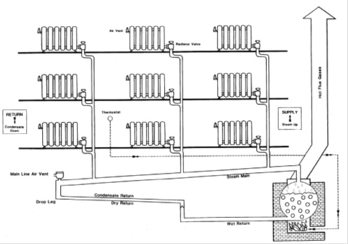
Figure 1: Schematic of one type of single-pipe steam system
Large differences in steam arrival times, excessively short boiler cycles, lack of zone control or temperature averaging or other type of interior sensors, and variable steam main lengths can all contribute to uneven heating in a building. When considering how to solve these issues, the following factors should be assessed.
Main Line Air Vents
Main line air vents serve to rapidly vent large amounts of air from steam lines. When a boiler begins its fill cycle, the vents lower the air pressure and aid the flow of steam down the main distribution pipes. In the absence of properly sized main line vents, steam produced in the boiler must push air ahead of it through the radiators. As a result, radiators closest to the boiler fill with steam faster than those further away and heating is uneven system-wide. This is exacerbated if the boiler shuts off before the whole system is full of steam.
One or more main line air vents is needed per steam loop to purge the build-up of air and control the speed of steam delivery to radiators throughout the building. The vents should be installed on the main distribution lines after the last riser and before the dry return drops into the wet return (condensate) piping. The valve remains open until the steam reaches it, at which point it shuts off to prevent steam from escaping through it.
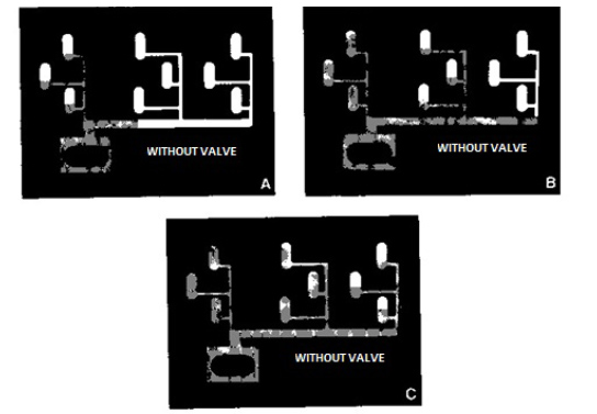
Figure 2 illustrates the steps in a boiler firing cycle without main line valves. At the beginning of a boiler firing cycle, the piping system and radiators are filled with air, which appears white in diagram A. Diagram B illustrates the system as steam heats the large mass of piping and pushes air out of the line toward the radiators. As shown in C, without adequate main line vents, a boiler may shut off before steam reaches the furthest radiators.
Data for the main line piping consisted of:
A census of all the main line loops in the building
• The approximate length of each main line loop
• Diameters of each section of pipe for each main line loop
• Pipe insulation for each main line loop
• Positions of vents on each main line loop
• Sizing and condition of main line vents.
• Diameter and length of building risers
• Sizing and condition of riser vents
The ground level was inspected and the number and condition of the main line air vents was determined for the building. Vents are often hidden in unused basements or hidden above finished ceilings and the latter is indeed the case at Waters Edge. So while a thorough inspection could be conducted to assess the current efficacy of the venting, diameters and lengths of a few sections of inaccessible piping were estimated. This information was used to determine the specifications for the type, quantity and placement of venting for the main steam lines.
Existing Conditions
The steam distribution at 700 Shore Road consists of a header at the boiler and two large trunks that branch into four major loops that bring steam to all the risers in the building.
For the sake of simplicity and clarity we will call these loops one, two, three and four.
Loop one supplies steam to the risers for apartments on the southwest part of the building.
Loop two supplies steam for apartments on the northwest part of the building.
Loop three supplies steam for apartments on the northeast part of the building.
And loop four supplies the remainder of the building southeast part.
Each loop consists of certain lengths of piping of different diameters. By calculating the volume of air in each different section, we were able to derive the volume of air in each entire loop.
Our objective is to vent the entire amount of air in each loop out of the line within one minute if possible (not more than two minutes) and at more or less the same time. To do this, we will need to install vents at the end of each loop that have the capacity to move this amount of air in this amount of time. Air vents are rated by the volume of air that they can vent in one minute (cubic feet per minute or CFM) at one pound per square inch pressure.